The metronome circuit of circuit below produces audible ticks from 40 ticks per minute to 400 ticks per minute by variation of one potentiometer. Gates one and two form a pulse generator, then R4 reduces the effect of battery voltage variation on the frequency so that once calibrated, the circuit maintains it.
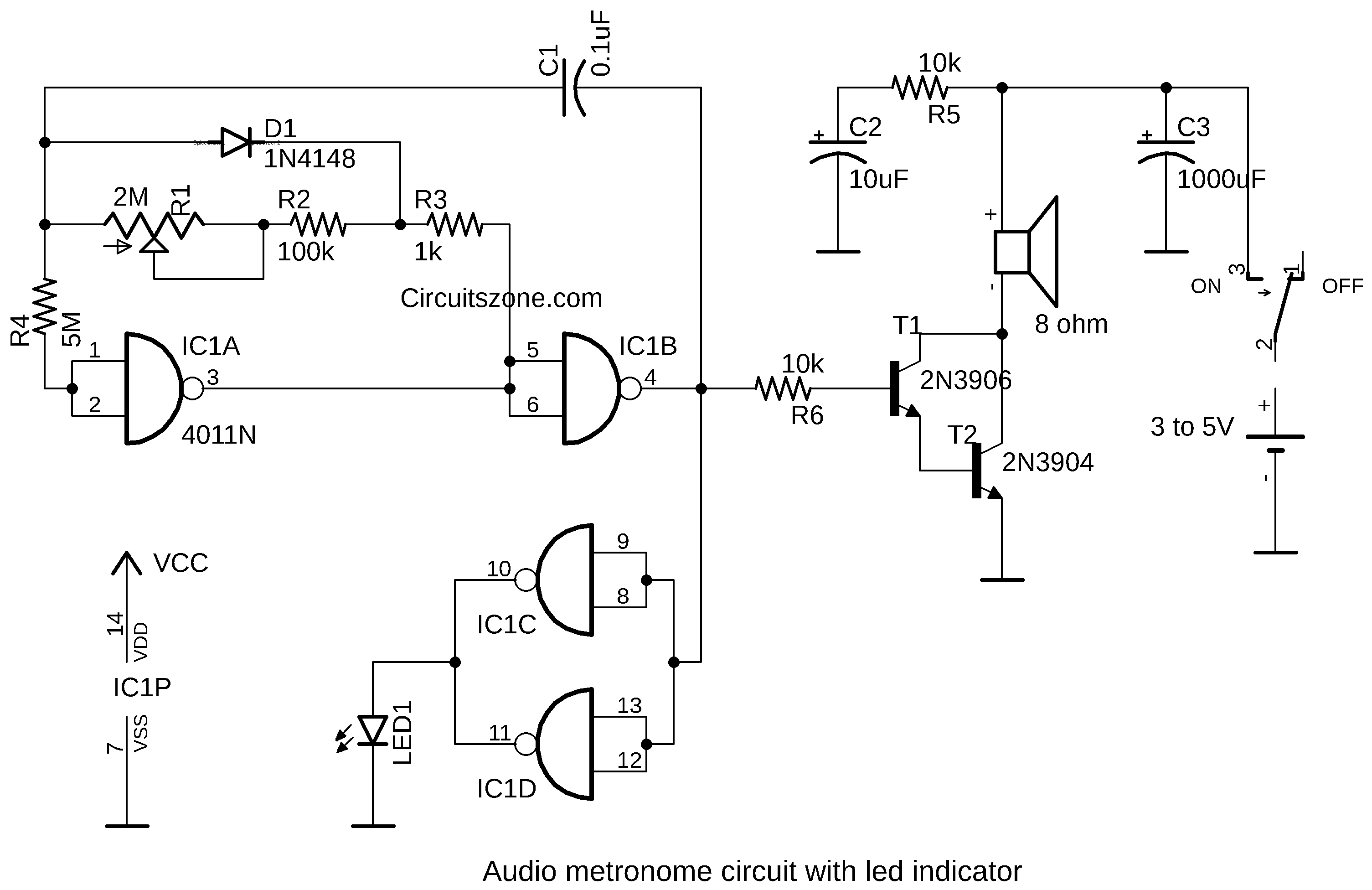
Transistors T1 and T2 will be amplify the pulses and produce loud ticks in the speaker. If required, a 100 ohms wire-wound potentiometer in series with the loudspeaker can be used as a volume control. The power consumption of the circuit is very small and the batteries will have a long life.
Then, a visual metronome with a flashing LED can be attractive solution. If you change of R3 to higher value, the pulse with can increase too. And hence gives a clearly visible flashing signal.
