To get good audio quality, tone settings must be considered, one of which is good bass and treble tones. For this reason, an automatic loudness control circuit is needed that effectively improves the audio quality before amplifying it by the amplifier.
This automatic loudness control circuit can vary the desired frequency response which is regulated by a potentiometer. This is to maintain an ideal hearing condition according to your ear.

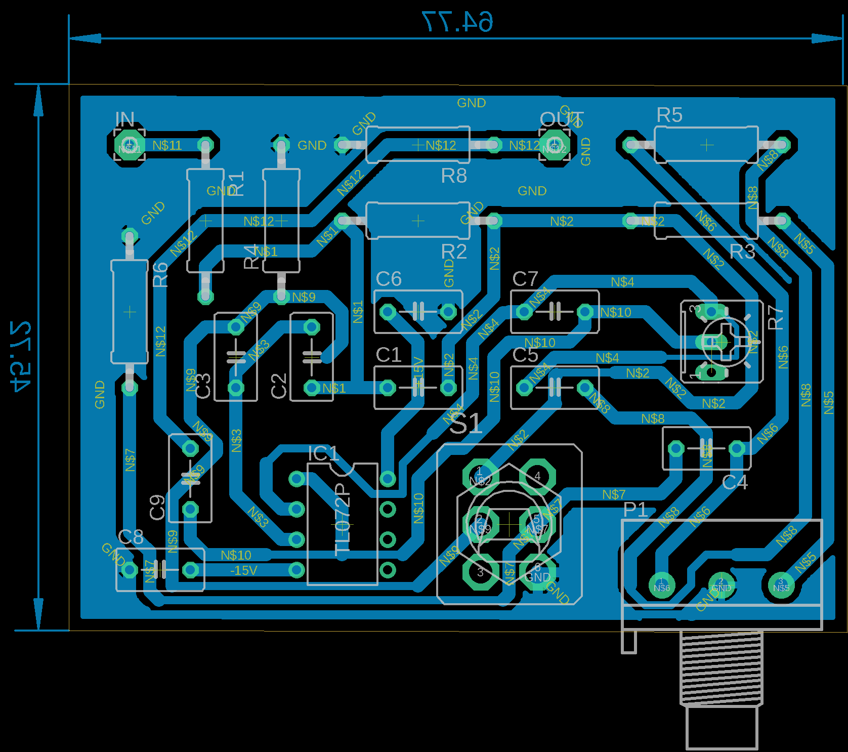

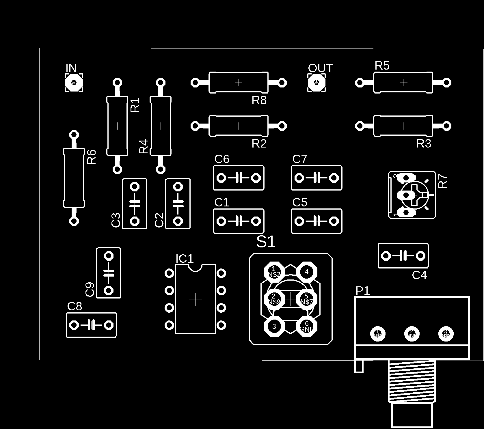
Part list:
P1 = 10K Linear Potentiometer (Dual-gang for stereo) R1,R6,R8 100K 1/4W Resistors
R2 =27K 1/4W Resistor
R3,R5 = 1K 1/4W Resistors
R4 = 1M 1/4W Resistor
R7 = 20K 1/2W Trimmer Cermet
C1 = 100nF 63V Polyester Capacitor
C2 = 47nF 63V Polyester Capacitor
C3 = 470nF 63V Polyester Capacitor
C4 = 15nF 63V Polyester Capacitor
C5,C9 = 1μF 63V Electrolytic or Polyester Capacitors C6,C8 47μF 63V Electrolytic Capacitors
C7 = 100pF 63V Ceramic Capacitor
IC1 = TL072 Dual BIFET Op-Amp
SW1 = DPDT Switch (four poles for stereo)
Capacitor C1 serves to increase low-frequency gain, while capacitor C4 increases high-frequency gain. However, for low-frequency gain, it depends on R2 and R5 for high-frequency settings.
When the S1 switch is OFF, the circuit will function as a pre-amplifier with a slight natural gain. For the gain of this pre-amplifier is set with the trimmer R7. The following is the frequency response to the potentiometer knob position.
The total harmonic distortion at all frequencies at this automatic loudness control is 1V RMS: <0.01%
Notes:
- Position S1 in the circuit is the normal position without loudness.
- The circuit shown in the figure is a series for mono channels, if it is to be made stereo then the
- circuit must be made in two, except for IC1, C6, and C8.
- The R7 must be adjusted for optimal sound but not distorted.
