Bass booster headphone amp circuit is a circuit that can improve the quality of the music from your audio device. especially in low frequency (bass). Bass booster headphone amp circuit can also improve the dynamics that will sound wonderful on your headphones or small speakers.
This headphone amplifier circuit using LM386 IC as the heart. This Chip is very well known and easy found on the market. LM386 IC requires only a few external components to work.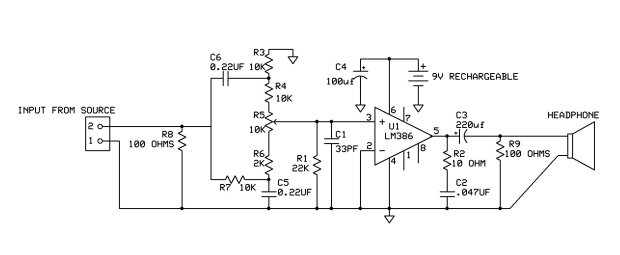
As seen in the figure, resistor R8 functioned as a burden to the source device. This is quite important because it will drown out the noise (noise) from the input source is not good. C6 and R3 serve as a high frequency filter, while R7 and C5 serves as a low-frequency filter.
Resistor R4 will limit the bass frequencies of up to 3dB, and resistors R6 will limit the “encouragement” of up to a maximum of 13dB. Capacitor C1 in a headphone amplifier circuit is a filter which is connected to the ground, where these capacitors will remove high frequency interference which is not desirable.
This headphone amplifier circuit can work well on the voltage 9VDC. This voltage can be found on the battery pack. So that the headphone amplifier circuit looks very compact and small.
