This disco audio mixer circuit is a typical example of the way modern components can, and do, simplify the realization of good quality audio circuits. In the given configuration it is eminently suitable for use as a disco audio mixer circuit, but the number of input channels can easily be enlarged.
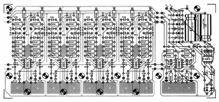
A can be seen in picture, in its basic form the audio mixer circuit has four input channels. These could, for instance, serve as inputs for a microphone, stereo pickup, and cassette player or tape recorder.
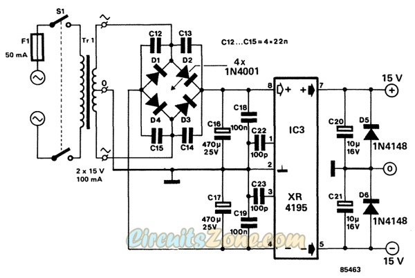
The power supply has been kept as simple as possible; if it proves difficult to obtain the XR4195 regulator IC, it may be replaced by a combination of 78L15 and 79L15. The transformer is preferably of the PCB type to keep the mixer as compact as possible.
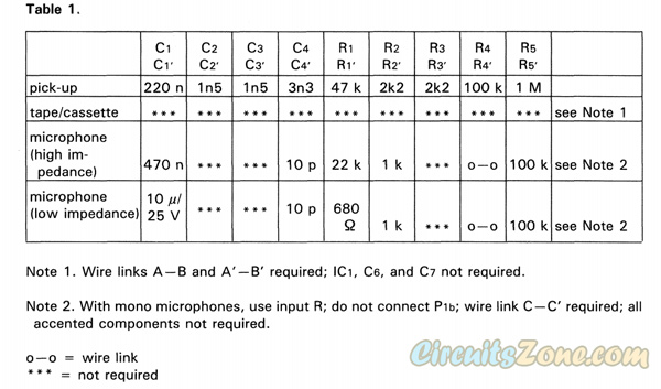
The values of C1 and R1 are dependent on the type of microphone used. If this is a high-impedance type, the values should be 470nF and 22k respectively, Whereas with low-impedance types, 10 uF and 680Ω are required.
Unfortunately, miniature bipolar electrolityc capacitors (C1, C1′, C9 and C9′) are not yet available everywhere, although they are almost indispensable in applications such as described here. Standard electrolytics may be used with maximum reverse voltages of 1 V, but their use introduces distortion and premature ageing (because of the reverse polatity).
Provision has been made on the printed circuit board for up to four channels. Two or more PCBs may be connected together; the output and supply sections may the be cut off as required.
Current consumption is about 10 mA per channel.
Disco Audio Mixer Circuit Diagram


Disco Audio Mixer Circuit Part List:
Resistors:
R1* . . .R5*,Rr* . . .R5’* = see table
R6*,R6’*,R8,R8′ = 47 k
R7,Ry = 22 k
R9*,R9’* = 100 k
Pia*,Pit>* = 22 k stereo slide potentiometer, log, 58 mm long
Capacitors:
Ci* . . .C4*,Cr* . . .C4’* = see table
C 5 *,C5’* = 470 n
C6*,C7*, C10,C11,C18,C19 = 100 n
C8,C8′ = 10 p
C9,C9′ = 10 uF/25 V
C12,C13,C14,C15 = 22 n
C16,C17 = 470 uF/25 V
C20,C21 = 10 uF/16 V
C22,C23 = 100 p
Semiconductors:
Di . . .D4 = 1N4001
D5,De = 1N4148
IC1* = NE5532 or LM833
IC2 = TL072
IC3 = XR4195
Miscellaneous:
Tn = mains transformer, secondary 2x 15V/100 mA
F1 = fuse, 50 mA, delayed action
Si = DPST on/off switch
Single-hole fixing chassis phono socket — 2 per channel
PCB 85463
*One of each required per channel.
This article reprinted from elector 303 circuits.
