A mixer is expected to have low-noise and high dynamic performance. Most standard mixers use in-verting operational amplifier. Unfortunately, the noise figure of many opamps is poor. and opamps with a good noise figure are normaly not suitable for operating with large signals.
The noise factor of standard circuits is often made even poorer because the source and amplifier are not properly mathed The characteristics of a mixer can be greatly improved, therefore, by the use of buffers at the input stages, and the constructing of operational amplifiers from good quality transistors. This has been done in the accompanying circuit.
The input is bufferes by T1 and T2. The input impedance of T1 can be ignored, so that the source merely needs to be matched with P1. The opamp is formed by transistors T3 to T8 incl. Good Quality RF transistors have been used in differential amplifier T3-T4-T5. These transistors have a better noise figure at a greater bandwidth AF types.
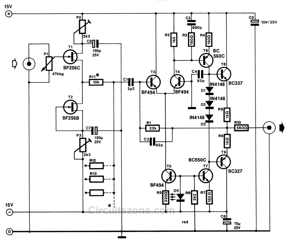
The proposed circuit has a frequancy range (-3 dBpoints) of 10Hz to 80 kHz; third harmonic distortion of not more than 0.005 per cent at 10 kHz and and output voltage of 9 Vpp; and signal-to-noise ratio of 100 dB.
The signal to noise ratio applies to an output signal of 9Vpp with open circuit input, and a bandwidth of 20 kHz. The maximum value of the output signal is about 12 Vpp, measured across a load impedance of 560 ohms. If the mixer is terminated by a higher impedance, the output voltage will be greater.
A further advantage of the circuit is that the popular valve sound may be realized in a simple manner. To this end it is necessary that T1 and T2 commence limiting at a slightly lower level, i.e. 12 Vpp input, than the composite opamp. The supply voltage of T1 and T2 then lie between ±6 VDC and ±9 VDC. Since T2 is connected as a current source, the exact supply voltage can be set with the 2k2 preset at the wanted clipping level.
If desired, the output off-set may be zeroed by inserting a 50 kilo-ohm preset in the base circuit of T4. This base should also be decoupled by a 1uF/63 V capacitor. The current consumption of the opamp is about 35 mA and that of the buffer stages not more than 10 mA. If, therefore, ten buffer stages are used, the power supply should be capable of providing 150 mA at ± 15 VDC.
