Whether it is for public address or for a band, a karaoke, microphone connection to an amplifier is a basic requirement. this Balanced Microphone Preamp circuit includes a 3-band equaliser and can be used to drive a guitar amplifier, any stereo amplifier or provide an additional channel for a public address amplifier. Balanced microphones are desirable since they prevent the injection of hum and noise into the sound system.
A balanced microphone has a 3-wire cable usually connected via XLR plugs and sockets. XLR pin 1 is the return or ground and the other two terminals (pins 2 & 3) are for the signals. The signals are in anti-phase; in other words when one line goes positive, the other line swings negative by the same amount. Any hum that is picked up along the lead is effectively cancelled because the same level of hum will be present in both signal lines.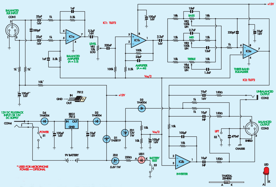
Microphone Preamp Circuit In control
The 3-band equaliser (bass, mid and treble controls) is handy for enhancing a musical instrument so that it sounds
natural when played through the microphone or to remove sibilance (the whistle sound from a voice, particularly when pronouncing the letter ‘s’) by reducing the treble level and boosting the mid range. or the bass control can
be reduced to suppress popping noises which occur when speakers hold the microphone too close. A level control is included to prevent overload and a ‘ground lift’ switch can reduce hum in some situations.
Microphone Preamp Circuit Parts List:

Microphone Preamp Circuit details
Let’s now have a look the circuit in ablove picture. It uses two low-cost op amp ICs, four potentiometers, an XLR
socket and plug, a 6.35mm jack socket, several switches and a few other lowcost parts. Op amp IC1a functions as a balanced-to-unbalanced preamplifier with a modest gain. The balanced microphone preamp circuit signal is fed to pins 5 & 6 of IC1a via 22µF capacitors and 1kΩ resistors.
Gain for the inverting input is set at 13.3 by the 3.3kΩ feedback resistor from pin 7 to pin 6. Frequencies above 48kHz are rolled off by the 1nF capacitor across the 3.3kΩ feedback resistor. For the non-inverting input (pin 5), the input signal is attenuated by a factor of 0.77 due to the 3.3kΩ resistor connecting to Vcc/2. Overall gain for this signal path is therefore 0.77 × 4.3 or +3.3. Thus, the signal gain for both signal paths is the same.
The 330pF capacitor between pin 2 and pin 3 of the XLR socket shunts high frequencies so that the reamplifier does not detect radio frequencies. The output of IC1a is fed to the Level potentiometer, VR1, via a 2.2µF capacitor and then to pin 3 of op amp IC1b. This provides a gain of 46 by virtue of the 100kΩ feedback resistor between pins 1 & 2 and the 2.2kΩ resistor to the half supply rail (Vcc/2). IC1b drives the following 3-band equaliser stage via a 2.2µF capacitor.
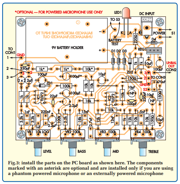
Microphone Preamp Circuit PCB Layout

Microphone Preamp Circuit EQ controls
The equaliser stage is based on opamp IC2a and potentiometers VR2, VR3 and VR4. These potentiometers and their associated resistors and capacitors are in the feedback path between pins 6 & 7. Each of the Bass (VR2), Midrange
(VR3) and Treble (VR4) feedback networks are effectively in parallel and act more or less independently (ie, with modest interaction).
When the tone pots are all centred, the microphone preamp circuit gain over their respective frequency ranges is unity (–1) and therefore the overall frequency response is flat. Let’s now look at the Bass control in more detail. When we wind
the wiper of VR2 fully clockwise towards the output of IC1b, the input resistance for IC2a now decreases to 18kΩ while the feedback resistance increases to 118kΩ. At the same time, the 15nF capacitor is completely in the feedback circuit across the 118kΩ resistance.
Without this capacitance the gain would be –118kΩ/18kΩ or –6.5 (ie, +16dB boost). The addition of the capacitor forces the circuit to give this gain below 100Hz and this reduces towards –1 as the frequency increases. Conversely, when the pot’s wiper is wound towards IC2a (anti-clockwise), the gain without the capacitor is 18kΩ/118kΩ or –0.15 (ie, –16dB cut).
The 15nF capacitor is now on the input side so the gain rapidly increases to –1 at frequencies above 100Hz. Maximum bass cut is below 100Hz. The Midrange section with VR3 works in a similar manner except that there is now a 12nF capacitor in series with the input. This combines with the
2.7nF capacitor across VR3 to give a bandpass filter.
The 220pF capacitor across IC2a’s feedback path provides high frequency rolloff to prevent instability. Similarly, the 1kΩ resistor at the inverting input acts as a stopper for RF signals to prevent radio pickup. IC2a’s output at pin 7 drives the unbalanced output at CON2 via a 10µF capacitor and 150Ω resistor.
IC2a’s output also drives pin 2 of the XLR output socket CON3, again via a 10µF capacitor and 150Ω resistor. Also, IC2a’s output drives inverting amplifier IC2b. This has a gain of 11 to derive the out-of-phase signal for pin 3 of CON3. The remaining pin on the XLR plug is the ground pin (pin 1). This is either directly connected to ground via switch S2 or AC-coupled to ground via a 470nF capacitor.
Opening the ground lift switch (S2) prevents a hum loop if the input is separately earthed. This is not likely to occur with a microphone but there may be separate grounds connected when the unit is used to convert a balanced line to an unbalanced output.

Microphone Preamp Circuit Power supply
Power for the microphone preamp circuit can come from a DC plugpack, internal 9V battery or via phantom power. Diode D4 provides reverse polarity protection for external DC power sources such as a plugpack. The DC supply rail is then filtered and applied to 3-terminal regulator REG1 to provide the +12V rail which is then fed to IC1 and IC2 via diode D2.
The internal battery supply is fed to the op amps via Schottky diode D1. A Schottky diode has a lower voltage drop than a standard diode and this extends the battery life. Note that the negative return of the battery goes via the DC power socket. Hence, the battery is disconnected whenever a plug is inserted into the DC power socket (CON 4). Phantom power is delivered via pins 2 & 3 of the XLR plug and applied via two 1kΩ resistors to diode D3.
Zener diode ZD1 regulates the voltage to 12V before it is applied to the rest of the circuit. This phantom power is usually produced from a source of either 48V with a 3.4kΩ impedance or from 24V with a 600Ω impedance. We can
draw up to 7.5mA from each supply or 15mA in total at 12V. Diodes D1, D2 & D3 isolate each supply so that only one source can deliver power to the circuit.
Essentially, where more than one supply is connected, it is the highest voltage source that powers the unit. The half-supply rail (Vcc/2) is obtained using two 10kΩ resistors connected in series across the power supply. The half supply point is decoupled using a 100µF capacitor to filter out any supply ripple.
Switch S3, LED1, ZD2 and the series 220Ω resistor form a simple battery test indicator for microphone preamp circuit. If the voltage is 9V, the voltage across the 220Ω resistor will be 9V 15.1V 11.8V (the LED voltage drop) or 2.1V. As a result, a current of 9.5mA will flow through LED1 when S3 is closed. This will cause the LED to glow brightly. As the battery voltage goes down, the current through the LED drops accordingly and so its brightness also decreases. For example, a battery voltage of 7.5V will only leave about 0.6V across the 220Ω resistor and so just 2.7mA will flow through the LED which will then be quite dim.
Microphone Preamp Circuit Testing
Apply power using a 9V battery and check that the battery test LED lights when the test switch is closed. Note that this LED will not operate if you are using a plugpack or phantom power. Test for 9V (when a fresh battery is powering the unit) or 12V when a plugpack is supplying power between pins 4 & 8 of IC1 & IC2. Further testing can be done with a microphone and amplifier. Check the operation of the level control and the equaliser controls. The ground lift should only be used when there is a hum present in the signal.
This microphone preamp circuit article reprinted from Everyday Practical Electronics, January 2007.
